| |
Bewehren der Schlitzwandlamelle
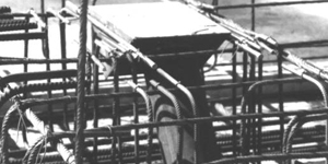
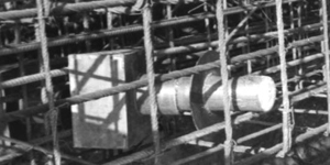
In jedes Schlitzwandelement wird ein durchgehender Bewehrungskorb eingehängt. Der Bewehrungskorb wird nach den statischen Erfordernissen bemessen und durch Schweißen oder Binden hergestellt. In dem Bewehrungskorb sind bereits Einbauteile, wie z.B. Rohre zur Durchführung von Verpressankern oder Anschlussbewehrung für Bauwerksdecken usw., vorzusehen.
Die Bewehrung von Decken oder Querwänden kann an die Schlitzwandbewehrung durch folgende Maßnahmen angeschlossen werden:
1. An dem Bewehrungskorb sind Stahlankerplatten angebracht, die nach dem Freistemmen an die Anschlussbewehrung angeschweißt wird
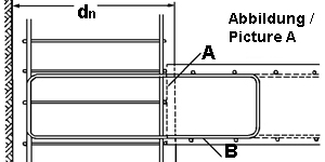
2. Die Anschlusseisen (Bügel) sind in den Bewehrungskorb hineingebogen und mit Styroporplatten ummantelt. Nach dem Aushub der Baugrube wird das Styropor herausgekratzt und die Anschlusseisen herausgebogen (Abb. A).
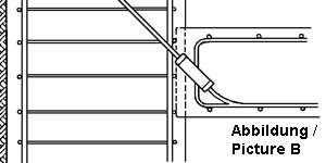
3 Der Anschluss durch Schraubmuffen (Abb. B) erfolgt.
Abb. A + B Ausbildung der Bewehrung für tragende Stahlbetonanschlüsse an Schlitzwänden . A Ausparung für Anschluss, B Anschlussbügel im Korb.
Alle Einbauteile sowie der Bewehrungskorb als ganzes müssen nach strömungstechnischen Gesichtspunkten konstruiert werden, damit der aufsteigende Beton diese Einbauteile auch wirklich voll umfließt und satt einbettet. Zur Sicherung der Betondeckung werden entweder feste Abstandshalter am Bewehrungskorb befestigt, oder es werden seitlich am Bewehrungskorb Führungsrohre eingebracht, die während des Betonierens gezogen werden. Der Bewehrungskorb darf nicht auf der Sohle der Schlitzwand aufstehen; er wird deswegen an der Leitwand aufgehängt. Bei großer Steiggeschwindigkeit des Betons und tief in den Beton eintauchenden Betonierrohren, muss die Bewehrung auch gegen Auftreiben gesichert werden.
|
Reinforcment the slottetwall lamella
Into every slottet wall element a continuous arming basket is hung up. The arming basket is calculated according to the static requirements and manufactured by welding or linkage. In the arming basket fittings, as e.g. tubes for the realization of grout anchor or connection arming for construction covers and so forth, are already to be planned.
The arming of covers or partitions can be connected to the slottet wall arming through following measures:
1. At the arming basket steel lever plates are attached, that after the stem free onto the connection arming is welded on.
2. The projecting reinforcements (Ironing) are bent into the arming basket and coated with polystyrene plates. To the excavation of the pit that is scratch out the polystyrene and bent the projecting reinforcements (fig. A).
3 The connection through threaded sleeves (fig. B) occurs.
Fig. A +B training of the arming for supporting reinforced concrete connections to slot wall . A reeces for connetion, B Connection bracket inside the basket.
All fittings as well as the arming basket as whole one must be constructed according to current-technical points of view so that the concrete going up surrounds these fittings fully also in fact and embeds these fittings fully. To the protection of the concrete cover firm spacers are attached either to the arming basket, or leadership tubes which are pulled during the concrete work are inserted on the side at the arming basket. The arming basket must not get up on the sole of the slot wall; it is hung up therefore at the leading-wall. With great footpath speed of the concrete and deep concreting-tubes dipping into the concrete, the arming must be protected also against floating.
|
|